Article Detail
22 Mar
IGBT TESTING
Most manufacturers IGBT devices are 100% tested before shipping and guaranteed to meet the published parametric data. We generally do not recommend re-testing by the customer because of the potential of damaging the device. If it is necessary to assess the electrical characteristics of the IGBT the following tests can be performed:
General Requirements:
• Always use static (ESD) safe handling procedures and replace the conductive gate-emitter foam after testing.
• Never apply connector to emitter voltages greater than the IGBT's VCES rating and never apply gate to emitter voltages greater than the IGBT's VGES rating. When using a curve tracer, ramp the voltage up and back down for each test.
• Never apply a voltage greater than 20V to the collector-emitter with the gate terminal open.
• Avoid thermal shock. Never put a cold device on a preheated hotplate. The temperature should not increase more than 10 degrees C/min. Digital multi-meter (DMM) test procedure:
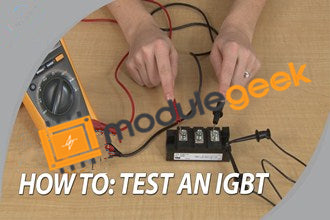
• Equipment Requirement – DMM with diode check mode and battery voltage less than 20V. (Typical units using 9V battery are OK).
• Collector-Emitter Junction test:
1. With the module out of circuit remove the conductive foam and short the gate to emitter.
2. With DMM in diode check mode, the collector to emitter should give a normal diode reading with positive on the emitter and negative on the collector.
3. The DMM should read open or infinite with positive on the collector and negative on the emitter. Damaged IGBTs may test as shorted in both positive and negative directions, open in both directions, or resistive in both directions.
• Gate Oxide test: With the DMM in resistance mode the resistance from gate to collector and gate to emitter should read infinite on a good device. A damaged device may be shorted or have resistive leakage from gate to collector and/or emitter.
Curve Tracer test procedure (Tests #1 & #2 require a high power curve tracer like Tektronix 371A):
1. Measure VCE(sat) with IC=IC(rated), Tj=25C, VGE=15V
2. Measure VF (free wheel diode) with IE = IE(rated), Tj=25C, VGE=0 (shorted)
3. Measure ICES with VCE=VCES , Tj=25C, VGE=0 (shorted)
4. Measure VGE(th) with VCE=10V , IC=IC(rated)/10,000

